10+ igbt block diagram
The output current first flows in the direction shown in the figure the IGBT T1 switches from ON to OFF while the IGBT T2 switches from OFF to ON after a short dead time. One is an optocoupler which electrically isolates signals.
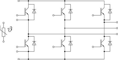
Semix305gd07e4 Semikron
ICP20 is empowered by NXPs.

. Tesla coil igbt solid state sstc schematic iv. Insulated Gate Bipolar Transistor IGBT Basics Abdus Sattar IXYS Corporation 1 IXAN0063 This application note describes the basic characteristics and operating performance of IGBTs. External components such as the IGBT module link capacitor bus bar and cooling plate are not included and must be provided by the customer.
The figure below is a block diagram which outlines a gate drive circuit. The Gate Collector and Emitter pins of the IGBT are marked below. Figure 1 shows a block diagram of a simplified switched-capacitor analog-to-digital converter ADC.
Download scientific diagram Block diagram of used IGBT driver IRS4427. C Block diagram of Excitation system of Synchronous Generator. Depends on what you want to test.
IGBT 1 and 3 are in ON state and 2 and 4 are in the OFF state and vice versa in fig8 state. 1 Providing -5V and 15V driving voltage for IGBT to ensure IGBTs turn on and off. Design and testing of user-configurable driving boards of pulsed xenon lamps with adjustable.
For this block diagram we will focus our attention on the DC Fast Charging DCFC Tier. Interest is very high for this solution for the obvious reason that waiting around for a battery to recharge. I am a student of Electrical Electronics Engg.
Block Diagram of TIDA-00917 This TI Design uses two reinforced isolated IGBT gate drivers. Preferably with a block diagram. A gate drive circuit is mainly composed of three sections.
Solid State Tesla Coil SSTC IV. It could be as simple as a 9V battery a pushbutton two resistors and a led. Circuit Diagram Block Diagram of IGBT tester too old to reply raju 2003-11-08 121636 UTC.
Diagram rice cooker block ih toshiba storage sub circuit using master. 3-phase motor control demonstration board featuring IGBT intelligent power module STGIPS10K60A Introduction This document describes the 1 kW 3-phase motor control. Vector control also called field-oriented control FOC is a variable-frequency drive VFD control method in which the stator currents of a three-phase AC or brushless DC electric.
Most modern audio converters use a switched capacitor architecture. 13 Block Diagram The block diagram for the TIDA-00917 is shown in Figure 2. General block diagram for a IGBT module and b IGBTDiode Source publication Design and Simulation of a Zero Crossing VSC Based Phase Synchronous Inverter for Microgrid System.
2 Having over-current protection to prevent the IGBT from being damaged when the current is. The below diagram shows the internal circuit of IGBT which includes two BJT and one MOSFET and a JFET. IR2110 Functional Block Diagram IR2110 Parameters IR2110 Features Floating channel designed for bootstrap operation Fully operational to 500 V Fully operational to 600.
I have been given IGBT Tester as. I would start looking at various.

Igbt Symbol Circuit Characteristics Constructional Diagram Etechnog

Igbt Insulated Gate Bipolar Transistor Electronic Circuit Projects Electronics Basics Transistors

Igbt Driver For 2 Level And 3 Level Industrial Applications With Enhanced Isolation Capability For Dc Voltages Of Up To 1500v Semikron

Igbt Switching With Cable Load Semikron

Wind Energy Application Examples Semikron

Update 3 How To Build The Simplest Dc Motor Speed Controller Using Mosfet And Potentiometer Youtube Motor Speed Circuit Diagram Diy Electronics

What Is The Function Of Igbt Quora

Igbt Driver For 2 Level And 3 Level Industrial Applications With Enhanced Isolation Capability For Dc Voltages Of Up To 1500v Semikron

What Is A Rectifier Block Diagram Working Principle Etechnog

Igbt Symbol Circuit Characteristics Constructional Diagram Etechnog

Igbt Switching With Cable Load Semikron

The Schematic Diagram Of The Induction Heater With Igbt S Induction Heating Circuit Diagram Induction

How To Make Igbt Driver Circuit Mosfet Driver Circuit Youtube Circuit Diagram Circuit Drivers

Igbt Symbol Circuit Characteristics Constructional Diagram Etechnog

Wind Energy Application Examples Semikron
What Is Igbt Structure Explained And Disassembled

What Is Igbt Structure Explained And Disassembled